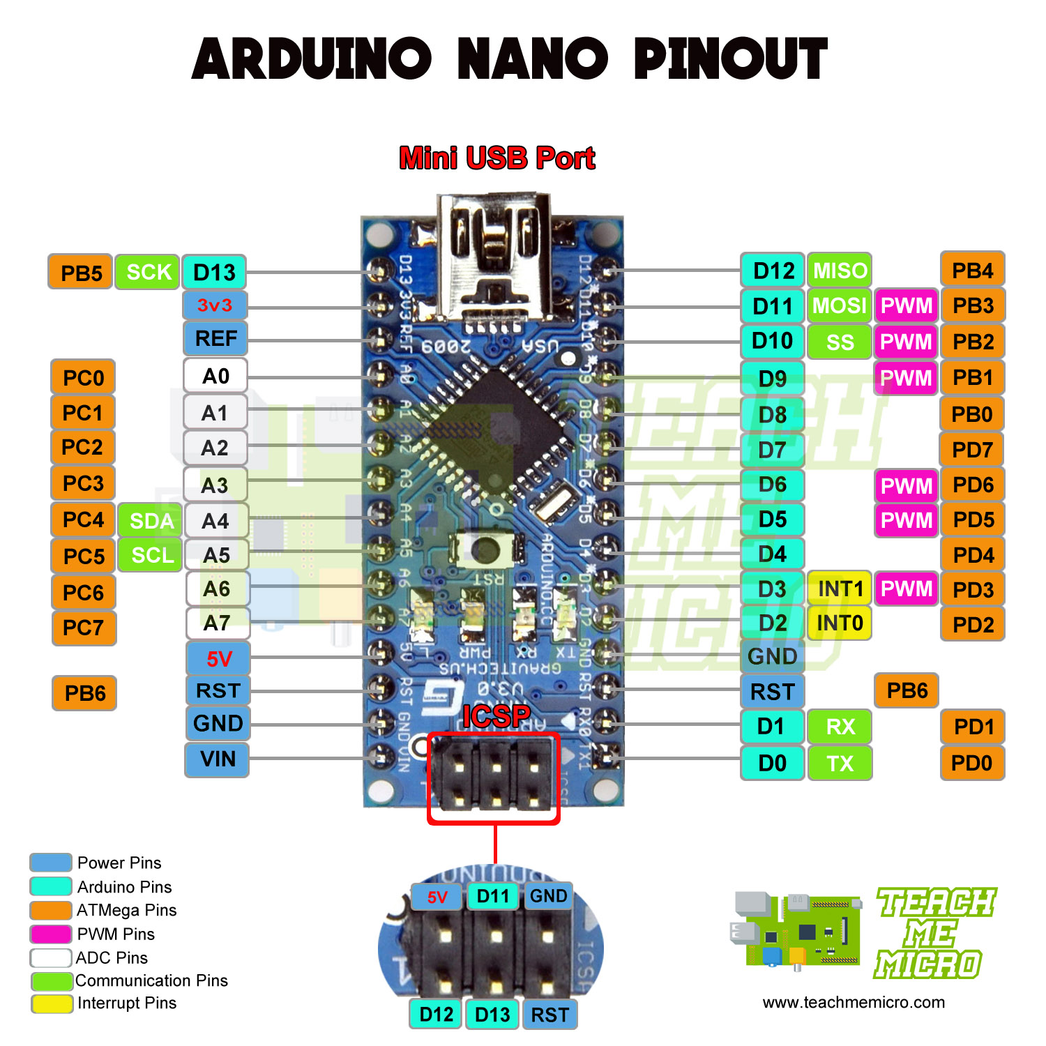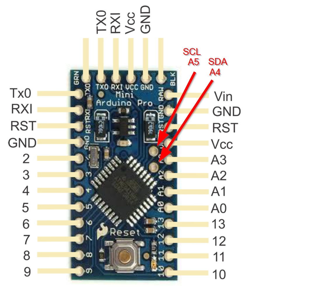

Atmega32U4 pinout: The atmega32U4 microcontroller chip has 44 pins and comes in a TQFP package. RESET: This pin is used to reset the microcontroller.ĭTR (Data Terminal ready): This pin is used to reset the board and enter the bootloader for programming the Arduino pro-mini. It is a low-power 8-bit AVR RISC-based microchip that features a 32KB self-programming flash program memory, 2.5KB SRAM, 1KB EEPROM, USB 2.0 full-speed/low-speed device, 12-channel 10-bit A/D-converter, and JTAG interface for on-chip-debug. When the pin is set to LOW or 0, the LED turns OFF. When this pin is set to HIGH or 1, the LED turns ON. LED: In the board, there is a built-in LED connected to digital pin 13. That’s why it is known as a data line, while SCL is called a clock line.

It is defined as the line used by the slave and master to send and receive data.
Arduino pro micro pinout serial#
The Serial Clock is initiated by the master device. It is used to adjust the shift of data between the two devices. It is defined as the line that transmits the clock data. The I2C uses two lines to send and transmit data: a serial clock pin uses (SCL) and a serial data (SDA) (SDA) pin. It is the two-wire serial communication protocol. These digital pins can be configured as an input or output using the pinMode (), digitalWrite (), and digitalRead () functions. This kind of input/output is usually called digital (or binary) and these states are referred to as HIGH or 1 and LOW or 0. The Arduino digital pins can read/output only two states: when there is a voltage signal and when there is no signal. There are 14 digital I/O pins (0-13) out of which 6 are PWM pins. GND: There are three GND (Ground) pins present on the Arduino Pro Mini board. We can change the voltage supplied voltage to 5V depending on the versions of the board. VCC: It is the regulated voltage of 3.3V. The supplied voltage at this pin can range anywhere between 3.4 to 12V. RAW: RAW is the unregulated input voltage that is supplied to the regulator. This button generates a low-level signal at the pin which is used to reboot the microcontroller.
Arduino pro micro pinout code#
It consists of 32 KB of flash memory for storing the program code (0.5 KB is used for storing the bootloader), 2 Kbytes of SRAM, and 1 Kbytes of EEPROM. The ATmega328 microcontroller is a high-speed, power-efficient AVR 8-bit microcontroller. EEPROM: 512 bytes Are you a beginner? Can't decide which book to read? Check out this article on Best Arduino Books for beginners Arduino Pro Mini Pinout details: ATmega328 microchip:.Note: Older version of the Pro Mini had the following specs that are different from the latest version: Given below are the technical specs of Arduino Pro Mini: Microcontroller ATmega328(latest version) Operating Voltage 5V and 3.3V Input Voltage 5 – 12 V (5V model) and 3.3 – 12 V(3.3V model) Digital I/O Pins 14 Pins (6 are PWM output pins) Analog Input Pins 6 Pins DC Current per I/O Pin 40 mA Flash Memory 32 kB (0.5 kB is taken by bootloader) SRAM 2 Kbytes EEPROM 1 Kbytes Clock Speed 16 MHz (5V model) and 8 MHz (3.3V model) Arduino Pro Mini Specs Table Image Source: Arduino Website Specifications of Arduino Pro Mini: NOTE: the ground on the left has moved down one pin.


 0 kommentar(er)
